Walkthrough: Create UA Wrapper |
Configuration of the CommServer UA to wrap OPC DA server is a straightforward process, which can be done in 5 steps:
Connect to OPC server using OPC Viewer.
Create online subscription in OPC Viewer.
Export address space to a dictionary file using OPC Viewer.
Create new project in UA Address Space Model Designer and choose configuration plugin.
Import OPC DA address space and build the model.
OPC Viewer is a free software tool that is very useful for developers, testers, integrators, and other users of the OPC. OPC Viewer has the functionality of saving the current configuration in a file called session. UA Address Space Model Designer is a user-friendly tool supporting all aspects of the model designing process. |
CommServer is installed (CommServer can be downloaded from here)
CommServerUA is installed (CommServerUA can be downloaded from here)
Before installation of the CommServerUA make sure that the following software is installed on your computer:
|
To start OPC Viewer, select:
Start Menu -> All Programs -> CAS -> CommServerUA -> OPC Viewer (OPC DA Classic Client)
The main window appears.
To connect to OPC Server, click “Browse network” icon (
 ) in the menu. The Select Server window appears (Figure 1); select OPC Server from a local or remote computer (e.g. CAS.CommServer.OPC.Da.Server):
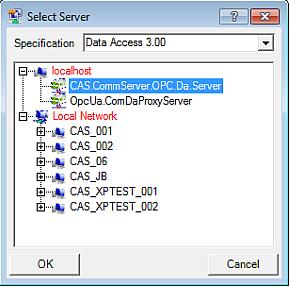 Figure 1: OPC Viewer – Select Server window
Select the computer and check what servers are available (to check available servers click on “+” next to the computer name).
 Note
NoteRemember to configure DCOM properly before connecting to the other computer.
The added OPC server is not connected (
 )
)
You can add a multiple OPC server to the configuration. It can be also the same OPC server or any other OPC server.
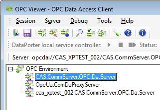 Figure 2: OPC Viewer – multiple OPC servers
Click the right mouse button on the added server and select “Connect” from the context menu or click “Connect to Server” icon (
 ) on the toolbar.
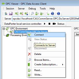 Figure 3: OPC Viewer – Connect
After successful connection to the OPC server, the icon changes to

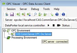 Figure 4: OPC Viewer – successful connection Note
If OPC server is not connected, an offline subscription can be created.
To check the status of the connected OPC server select “View Status” from the server node context menu or click icon (
 ) on the toolbar.
The Server Status dialog appears:
) on the toolbar.
The Server Status dialog appears:
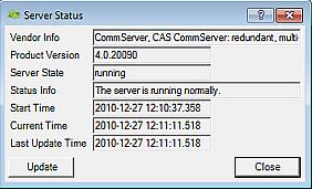 Figure 5: OPC Viewer – Server Status
To create a subscription, click the right mouse button on the connected OPC server and select “Create Subscription...-> Browse server…” from the context menu. Create Subscription dialog windows appears. Provide the subscription name and click on “Next” button to continue.
Browse a tree view on the left pane (Figure 6) and select requested items. To add an item to a subscription, double click on the item name. When all requested items are added, click on the “Next” button. In the next window, verify the subscription settings (e.g. scanning rate or name) and click on “Done”.
NoteIn the process of the UA Wrapper configuration it is recommended, but not required , that all server items are added to one of the created subscriptions.
 Figure 6: OPC Viewer – adding tags
Items added to the subscription appear in the OPC viewer main window (Figure 7).
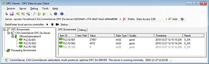 Figure 6: OPC Viewer – added items
Finally the subscription must be saved as a session file (*.oses) by choosing “Session -> Save” from the menu.
Click the right mouse button on the selected OPC server node and select “Browse Items...” from the context menu. Address Space Dictionary Management dialog appears.
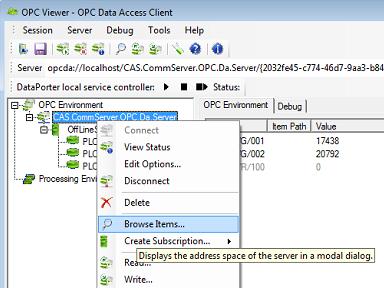 Figure 8: OPC Viewer – Browse server items
Click the "Save" button (Figure 9). In the window that appears, choose "Dictionary files (*.odic)" in the "Save as type" drop-down list and choose location of the *.odic file, where the address space will be saved.
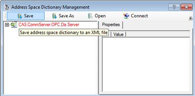 Figure 9: OPC Viewer – Saving the server address space in a dictionary file
The created session file and dictionary file will be further used by the Address Space Model Designer to automatically create configuration for the CommServerUA.
1To launch Address Space Model Designer select:
Start Menu -> All Programs -> CAS -> CommServerUA -> OPC UA Address Space Model Designer
After first launching of the UA Address Space Model Designer, the "Help" panel with version history is being displayed. Click on the "Main" panel to manage the solution content.
To create new project select “Solution -> Add Project ->New” from the context menu (Figure 10).
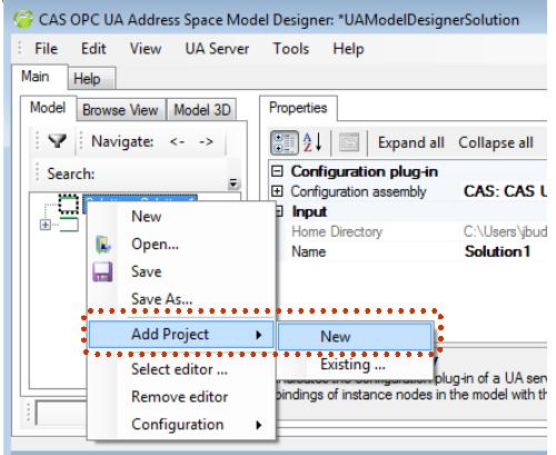 Figure 10: UA Address Space Model Designer – Create new project in the solution
Open CommServerUA configuration editor using UA Server menu (figure 11). The default location of this editor is:
%USERPROFILE%\My Documents\UAAddressSpaceModelDesigner\Sample
After clicking on the "Open" button the "UA server configuration file" dialog appears. In this walkthrough the configuration is created from scratch using default setting, hence click the "Cancel" button to skip opening a file.
For more information about using plugins as external configuration editors see UA Server configuration.
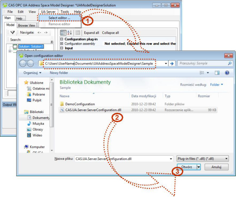 Figure 11: UA Address Space Model Designer – Select configuration editor
To import address space from DA server to UA model click the right mouse button on the context menu of the "Solution -> Project -> Domain" and select "Import -> From OPC DA ...".
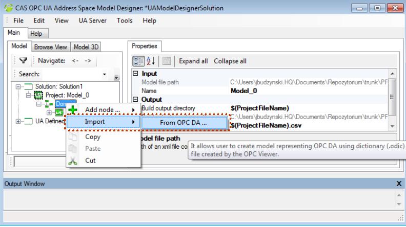 Figure 12: Import from OPC DA
After clicking on the "From OPC DA ..." you will be asked to open dictionary file (*odic) created above, so choose the file that you have created in section 3 Then you will be asked to choose session file (*oses), so choose the file that you have created in section 2.
Finally you get the fully functional model with the data bindings. Now you can build the model and get all configuration files required for launching CommServerUA.
To build the model you need to select "Tools -> Build/Verify -> Build Solution" from the menu bar. Before starting the build operation you will be asked to save the solution file, model file, configuration file and *.csv file (if you did not save those files earlier).
If there are any problems with Build process, check if all files have correct names and locations and if there are still problems - reset UA Address Space Model Designer options to default values ("Reset" button is in "Tools -> Options"). |
Now you can use CommServerUA with the configuration similar to your old OPC Classic server.