Walkthrough: Proces DataBinding |
In this walkthrough you will select a dedicated UA server configuration editor and add/modify real-time process data-bindings of the selected model nodes.
By default, the Address Space Model Designer is installed with a sample solution. This solution contains a project with the model of a boiler. This model is described in the Boiler Model topic.
Architecture of the Address Space Model Designer allows vendors of the UA servers to develop plug-ins providing a configuration editor. The editor is used to modify the general settings and define model nodes data-bindings with the real-time process.
The dialog boxes and menu commands you see might differ from those described depending on your active settings or edition. To change your settings, choose Options on the Tools menu. For more information, see Getting Started. |
After starting of the OPC UA Address Space Model Designer:
Open the solution if not opened yet (for more details see: How To: Open Sample Solution)
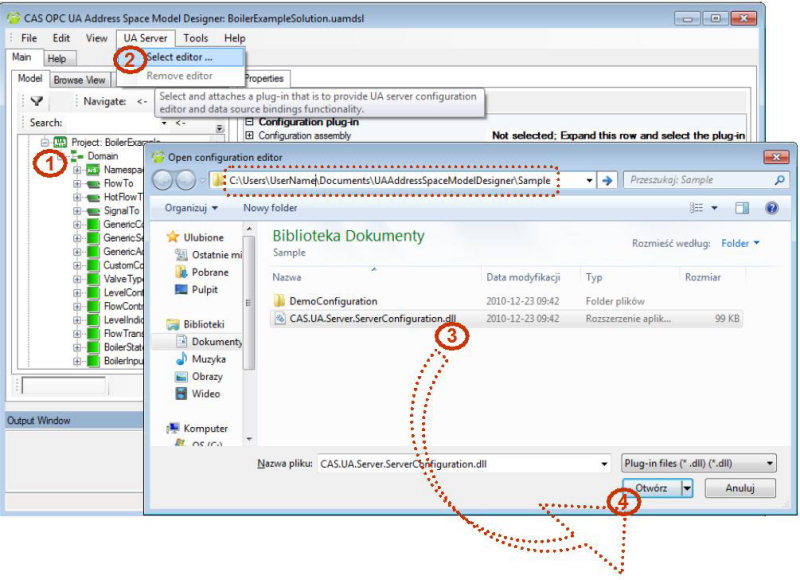
Select "Select Editor ..." in the UA Server menu (see Pt 2 in the figure below). The dialog Open Configuration Editor is then displayed.
Using the Open Configuration Editor dialog box open the vendor specific plug-in providing the server configuration functionality (see Pts 3 in the figure below), i.e. implementing necessary interfaces. The default location of the configuration plug-in for CommServer UA is installed with the sample solution.
Confirm using the Open button (Pt 4 in the figure below).
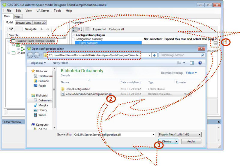
Alternatively, you can select the UA server configuration editor using the solution properties, as in the figure below:
In the sample solution, a configuration file for the editor is pre-selected. The configuration file contains general server settings and information how to bind the address space nodes with the underlying real-time process. To change the configuration file follow the procedure below.
Select the configuration editor if not selected yet (the section above).
Using the UA Server configuration file dialog box that appears, open the server specific configuration file providing the setting needed to setup the server at startup and runtime (the figure below).
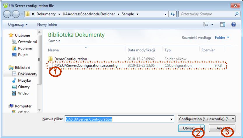 Figure 3: Select configuration file
After selecting the configuration file and selecting Open button (Pt 2 in the figure above) settings can be edited using an editor provided by the plug-in assembly.
If the Cancel button is clicked the information dialog as below appears:
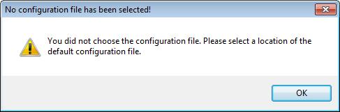 Figure 4: Information when no configuration file is selected
Next, the "Select folder dialog" appears. In this window, select the folder where the default configuration will be saved.
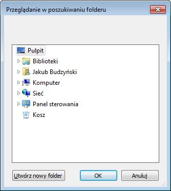 Figure 5: Selection of the folder, where the default configuration will be located
If the folder is selected and the OK button is clicked, the default configuration will be created in this folder, otherwise (if the Cancel button is selected) the information dialog will appear:
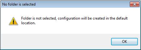 Figure 6: Information when no folder is selected
Select the configuration editor and configuration file if not selected yet (as described above).
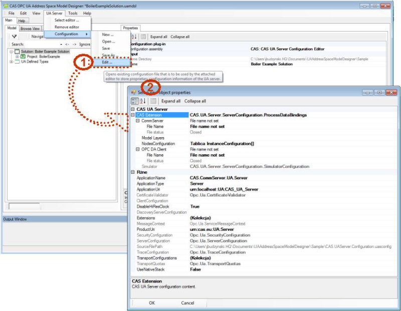
Select Configuration/Edit … in the UA Server menu. The editor dialog is then displayed as below.
Alternatively, you can select the UA server configuration editor using the solution properties.
One of the most common scenarios for UA server deployment is to set process data-bindings. To set and edit the process data-bindings you can use:
UA Server in the main menu.
Context menu for the selected node.
Property grid for the selected node.
In the described procedure, the UA Server entry is used. |
The dialog boxes and menu commands you see might differ depending on the server configuration editor used. |
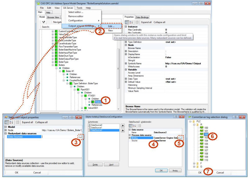
In the example below there are preconfigured data-bindings for some nodes. E.g. the Boilers node contains two data sources configured. This means that the UA server will use the configured data-sources as sources of values for all boilers. The meaning of the data-bindings for the objects is vendor specific.
Browse to the Boilers | Boiler1 | InputPipe | FlowTransmitter1 | Output variable (see Pt 1 in the figure below).
Select Output: process bindings | Edit …. in the UA Server menu (see Pt 2 in the figure below). The dialog provided by the selected configuration editor plug-in is then displayed.
The dialog provided by the CAS CommServer UA™ configuration editor displays two properties groups:
Model
Redundant Data Sources
Properties from the Model group are read only and present a description of the node
To define new and edit the existing process data-sources click the (…) button (see Pt 3 in the figure below) on the right side of the (DataSources) property located in the Redundant Data Sources group. The dialog DataSourceConfiguration Collection Editor is then displayed.
Use this dialog to create new and edit the existing data-bindings. In a drop-down list (Pt 4) different DataSources can be found (including CommServer, OPCViewer, Simulator or other, vendor specific). After choosing CommServer as DataSource, there appears the dialog, where CommServer configuration file (default is DefaultConfig.xml) should be selected, and after choosing OPCViewer as DataSource - the dialog, where OPCViewer session file (default is DemoConfiguration.oses) should be selected.
After clicking on the (...) button (Pt 5) the dialog with CommServer tags or OPC Viewer nodes appears.
Select a proper tag from the list (Pt 6 - an example of CommServer tags) and confirm with OK button (Pt 7).