MODBUS IP configuration |

Select TCP or UDP as protocol. Socket number settings are ignored and can be set by default as –1 (this setting is valid only for slave sides of the protocol).

CommServer allows us to tune the timeout settings that are used in the Modbus DataProvider. The following settings are available:
InterframeGap - period of time in milliseconds between consecutive request frames
MaxNumberOfRetries - maximal number of retries getting the response. After this limit has passed the base station finds that communication with the device using current interface coupled with this protocol is broken and it activates the next interface in the pipe if available. The failed interface is marked inactive and will remain in this state until the defined (as “inactive time after failed”) timeout expiration.
ResponseTimeOut - maximal time of waiting for the response from a remote device
Timeout15 - maximal wait time in microseconds for the next character inside Modbus telegram (Modbus specifications defines this time as time of 1.5 character that goes through the communication layer, but due to Windows limitation it is not recommended to set this timeout to less than 11 milliseconds)
Timeout3 - maximal wait time for the next character while waiting for the response frame end (a silent interval separating message frames, e.g. 3.5 character times for Modbus)
The default settings are optimal for communication over the serial link; if TCP/UDP transportation it is recommended to tune the settings. |
It is necessary to set a valid segment address. This address is the address of the PLC that we want to connect to. Below there is an example of connection settings to PLC. In this case TCP is used:

The syntax of the segment address is:
server_IP_address:port_to_which_commserver_establish_the_connection
In the figure below there is an example connection to PLC, whose IP address is 192.168.0.8 and communication port is 2101:

Modbus DataProvider reads the data in blocks. Requests are sent to the device (called station in the CommServer configuration) that has an address (according to Modbus protocol) set inside port (interface) definition. The user can freely define a block of data to be read. The block of data is received as an answer from the device.
During the configuration of the data block, the following settings must be configured:
Address – the initial address of the block
Data Type – the address space in the device to be read (available address spaces are: Coils, Discrete Inputs, Holding Registers, Input Registers, Memory Bank Registers , 8 bits Holding Registers )
Name – the name of the data block in the CommServer configuration (not used during communication)
Tags collection – tags definitions inside the block. Each tag has:
Name – the name of the tag inside the OPC server address space
Access Rights - indicate if this item is read only, write only or read/write. This is NOT related to security but rather to the nature of the underlying hardware
DataTypeConversion - conversion requirements. Data will be available in the required type (if conver-sion is possible).
In Modbus protocol, the block address indicates the offset of a particular element within its address space (e.g. holding register, coils, etc.), but this offset may not be equal to physical address of this element in the memory. An example of such situation is a Modicon 984 controller, where:
Register at reference 0 is address 40001 in Modicon 984
Coil at reference 0 is address 00001 in Modicon 984
That’s why sometimes it is necessary to change the address to offset (e.g. subtract 40001 when a Holding Register is concerned) and finally the offset (not address) must be inserted to the CommServer block configuration.
The Modbus DataProvider supports also some extension to Modbus protocol, e.g.:
32-bit Holding Register
Floating point values
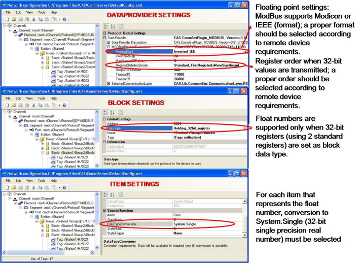
In Modbus, a 32-bit register is transmitted as two standard (16-bit) registers. There are two modes of how 32-bit registers are transmitted. In the first mode (usually called Modicon), the first register contains bits 15 - 0 of the 32-bit number, and the second register contains bits 31 - 16 of the 32-bit number. In the second mode (called inverted), the order of those two registers is inverted. The Modbus DataProvider supports both modes and the mode can be selected in DataProvider settings in the RegisterOrderIn32mode property (see figure below).
In case of the necessity of using 32-bit Holding Register, a special block data type must be selected: Holding_32bit_Register (see figure below). Note that floating point numbers are available only when 32-bit registers are used.
As far as floating point numbers are concerned, the proper floating point format must be selected. This DataProvider supports two modes: Modicon [standard: the first register contains bits 15 - 0 of the 32-bit number (bits 15 - 0 of significant), and the second register contains bits 31 - 16 of the 32-bit number (exponent and bits 23 - 16 of significant)] and IEEE (inverted: IEEE floating point number format is used). The mode can be selected in DataProvider settings in the FloatingPoint property (see figure below). What is more, conversion to System.Single must be set for each item that should be available in OPC as floating point number.
