Boiler model |
This topic contains the following sections:
Real-time Process
OPC UA Model
OPC UA Model Designer
Related Topics
Publication of process real-time data and metadata in the Unified Architecture Address Space requires a prior model design. OPC UA Address Space Model Designer software is intended to help developers and engineers to design OPC Unified Architecture models. The whole configuration can be prepared using a user-friendly Windows-based GUI. All nodes are presented on a tree and can be edited in the property window. This section contains an example that shows how to start from the real-time process and finish the design with a model in OPC UA Address Space Model Designer.
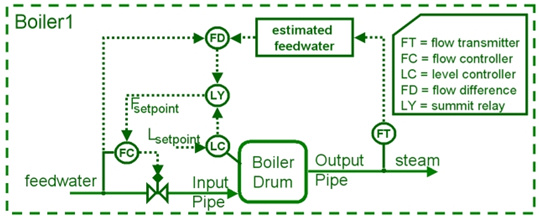
This example considers a real process in a boiler producing steam from water. The system (boiler) consists of:
input and output pipes
boiler drum
control module
sensors
The boiler is shown in the figure below
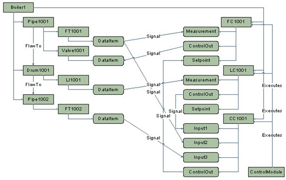
The first step is to prepare an OPC UA Address Space model diagram. A sample diagram that describes the a/m boiler is shown below.
Now we can port the design prepared in the previous step to the UA Model Designer. A sample design is shown below.
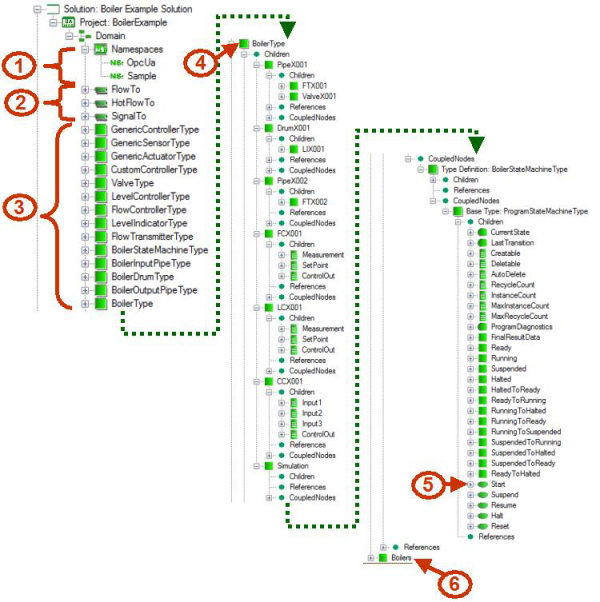
Namespaces – this model uses the standard OPC Unified Architecture namespace (OpcUa : http://opcfoundation.org/UA/) and defines an own namespace Sample (http://cas.eu/UA/Demo/).
References – this model defines three references. FlowTo and HotFlowTo are used to describe the flow of water and steam. SignalTo references are used to describe the flow of the signals in the boiler. An example of reference usage is shown in the figure below
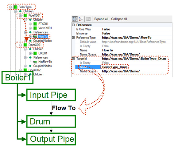 Figure 4: Reference
Types definitions – those are definitions of types used in the model. Each important object in the system being designed should have a type definition. Such a type definition includes information about what the type instance should provide (e.g. variables, properties, methods). This model defines many types for sensors, controllers, valves, etc. A sample Custom Controller Type definition is shown below. It contains properties with information about controller inputs, description of the controller and controlling process.
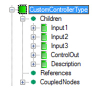 Figure 5: CustomControllerType
Boiler type – this is the type definition for Boiler (similar to definitions in item 3). This type includes all necessary objects in the system (e.g. input pipe, output pipe, drum, etc.).
Method definition – this model defines one method that is used to start simulation of the data in an instance of the type (BoilerType in this case).
Boiler – this is an instance of the boiler type; this node represents the real boiler (Boiler1).