CommServer configuration example |
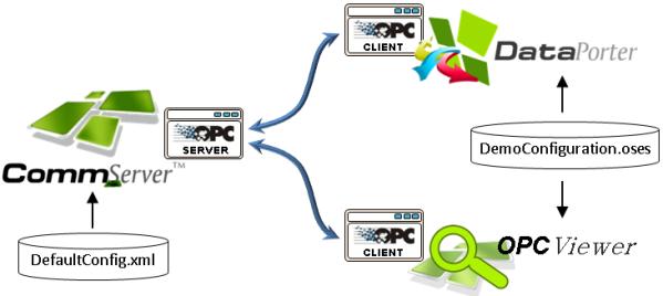
CommServer stores its configuration in an “.xml” file that contains information about channels, protocols, stations and data. The demo configuration shipped with CommServer is stored in the CommServer installation directory in the “DefaultConfig.xml” file.

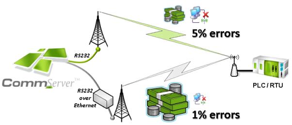
In this demo configuration, CommServer is responsible for reading data from one remote unit – called a station in CommServer terminology. This station and a protocol that is used to access the station are simulated by the DataProvider: DP.DemoSimulator – a CommServer plugin (separately distributed component) responsible for provision of real time process data. The station can be accessed via two communication routs:
Directly connected radio – standard serial communication is used and the station address is 0. The simulated error rate is around 5%
Radio connected via a leased line – it is necessary to use a port server that is available on IP 192.168.0.1 and TCP port number 2101, the station address is 0. Let's assume that the cost of this route is three times greater than that of the first one. The simulated error rate is around 1%
The communication diagram is presented in the picture below:

The system requires that the following data must be gathered:
Registers from address 100 to 110 that contain static values (floating point or integers). It is possible to write to those registers. It is required to gather those data every 1 second
Flags from address 100 to 109 that contain static binary values. It is possible to write to those flags. It is required to gather those data every 1 second
Read only registers from address 10000 to 10002 that contain random generated values. It is required to gather those data every 5 second
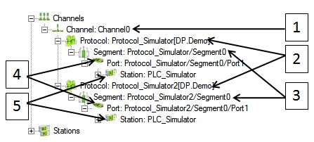
Take a look at the CommServer configuration in NetworkConfig:

The following elements can be found:
Channel – there is one configured channel named Channel0
Two protocols: DP.Demo – that is a simulator of the protocol and the remote device. The first protocol has ErrorFrequency parameter set to 20 (every 20th packet is lost, it is 5%). The other protocol has ErrorFrequency set to 100.
Two segments - the value of the segment address parameter is important in the second segment that is set to 192.168.0.1:2101 (CommServer should send a data stream to the IP address 192.168.0.1 and port number 2101, the TCP or UDP protocols can be set as a parameter in the production environment using a real DataProvider).
Port definition – this is quite an important part of the configuration; comparison of those two definitions is shown in the picture below:
 Figure 4: Comparison of those two definitions
Address is the same in both cases, same as station number (0). Inactive time – this time defines period of time for each interface in which the interface is in the inactive mode. After expiration, this interface switches off the active interface and changes its state to activate itself to check if it is still available. The switched off interface will preempt the communication after expiration of its InactTime. This solution guarantees that only one interface for the selected station is active at any instant and keeps this state as long as another interface becomes active. If there is only one interface it becomes active forever and no additional action is taken. The bigger value of this time, the more rarely this port (interface) is used, so this value should be greater for the more expensive route. The meaning of InactiveTimeAfterFailure parameter is exactly the same as InactTime, except it is used for scheduling after a communication failure occurs on this port. It is usually greater than inactive time (we do not want to try a broken connection). In this demo configuration this time is very short because all communication errors are simulated, connection is never broken, so we do not want to waste time.
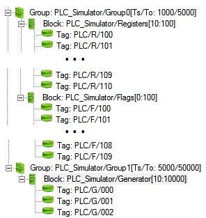
Station definition – here you can find information about what data and how often should be read. The same station is linked to both ports:
 Figure 5: Station definition
Here we have two groups defined. The first one is pooled every 1s (timeout 5s), the other one is pooled every 5s (timeout 50s). The first group contains two data blocks: writable registers from address 100 to 110 and writable flags from address 100 to 109. The second group contains one data block of read only registers from address 10000 to 10002.
This sample configuration, which is delivered with CommServer software family.