Graphical Notation |
This topic contains the following sections:
This topic defines a graphical notation for OPC Unified ArchitectureAddress Space data. This notation is used in other topics to expose examples of Address Space data. However, it is not required to use this notation to expose Address Space data.
The graphical notation is able to expose all structural data, their attributes including their current value and references between the nodes including the reference type can be exposed. The graphical notation provides no mechanism to expose events or historical data.
The notation is divided into two parts. The simple notation only provides a simplified view on the data hiding some details like attributes. The extended notation allows exposing all structure information of Address Space, including attribute values. The simple and the extended notation can be combined to expose the data in one figure. The following subsections describe the simple and the complex notation.
Common to both notations is that neither any color nor the thickness or stile of lines is relevant for the notation. Those effects can be used to highlight certain aspects of a figure.
Depending on their class nodes are represented by different graphical forms as defined in table.
Node Class | Graphical Representation | Comment |
|---|---|---|
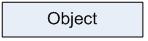 | Rectangle including text representing the string-part of the DisplayName attribute of the node. The font shall not be set to italic. | |
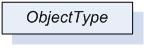 | Shadowed rectangle including text representing the string-part of the DisplayName attribute of the ObjectType. The font shall be set to italic. | |
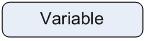 | Rectangle with rounded corners including text representing the string-part of the DisplayName attribute of the Variable. The font shall not be set to italic. | |
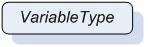 | Shadowed rectangle with rounded corners including text representing the string-part of the DisplayName attribute of the VariableType. The font shall be set to italic. | |
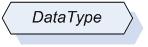 | Shadowed hexagon including text representing the string-part of the DisplayName attribute of the DataType. | |
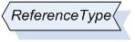 | Shadowed six-sided polygon including text representing the string-part of the DisplayName attribute of the ReferenceType. | |
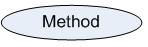 | Oval including text representing the string-part of the DisplayName attribute of the Method. | |
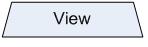 | Trapezium including text representing the string-part of the DisplayName attribute of the View. |
References are represented as lines between nodes as exemplified in Figure 1. Those lines can vary in their form. They do not have to connect the nodes with a straight line; they can have angles, arches, etc.

Table 2 defines how symmetric and asymmetric references are represented in general, and also defines shortcuts for some types represented by the ReferenceType nodes. Although it is recommended to use those shortcuts, it is not required. Thus, instead of using the shortcut also the generic solution can be used.
Type | Graphical Representation | Comment |
|---|---|---|
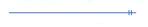
Any symmetric ReferenceType |  | Symmetric ReferenceType nodes are represented as lines between nodes with closed and filled arrows on both sides pointing to the connected nodes. Near to the line has to be a text containing the string-part (name fild of the QualifiedName) of the BrowseName of the ReferenceType. |
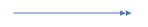
Any asymmetric ReferenceType |  | Asymmetric ReferenceType nodes are represented as lines between nodes with a closed and filled arrow on the side pointing to the targe node. Near to the line has to be a text containing the string-part ( name ) of the BrowseName of the ReferenceType. |
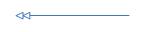
Any hierarchical ReferenceType |  | Asymmetric ReferenceType nodes that are subtypes of HierarchicalReferences should be exposed the same way as asymmetric ReferenceType nodes except that an open arrow is used. |
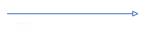
 | The notation provides a shortcut for HasComponent references shown on the left. The single hashed line has to be near the targe node. | |
 | The notation provides a shortcut for HasProperty references shown on the left. The double hashed lines have to be near the target node. | |
 | The notation provides a shortcut for HasTypeDefinition references shown on the left. The double closed and filled arrows have to point to the target node. | |
 | The notation provides a shortcut for HasSubtype references shown on the left. The double closed arrows have to point to the source node. | |
 | The notation provides a shortcut for HasEventSource references shown on the left. The closed arrow has to point to the target node. |
In the extended notation some additional concepts are introduced. It is allowed only using some of those concepts on elements of a figure.
The following rules define some special handling of structures.
In general, values of all data types should be represented by an appropriate string representation. Whenever a namespace index or LocaleId is used in those structures they can be omitted.
The DisplayName attribute contains the locale (LocaleId) and the text (String) fields. Such a structure can be exposed as [<locale>:]<text>; where the locale is optional. For example, a DisplayName attribute can be “en:MyName”. Instead of that, also “MyName” can be used. This rule applies whenever a DisplayName attribute is shown, including the text used in the graphical representation of a node.
The BrowseName contains the namespaceIndex (UInt16) and the name (String) fields. Such a structure can be exposed as [<namespaceIndex>:]<name>; where the namespaceIndex is optional. For example, a BrowseName can be “1:MyName”. Instead of that, also “MyName” can be used. This rule applies whenever a BrowseName is shown, including the text used in the graphical representation of a node.
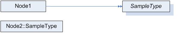
Instead of using the HasTypeDefinition reference to point from an Object or Variable to its ObjectType or VariableType the name of the target node of the HasTypeDefinition reference can be added to the text used in the node. It has to be prefixed with “::”. Figure 2 gives an example, where “Node1” uses a reference and “Node2” the shortcut. A figure can contain HasTypeDefinition references for some nodes and the shortcut for other once. It is not allowed that a node uses the shortcut and additionally is the source node of a HasTypeDefinition.
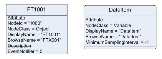
To display attributes of a node additional text can be put inside the form representing the node under the text representing the DisplayName attribute. The DisplayName attribute and the text describing the attributes have to be separated using a horizontal line. Each attribute has to be set into a new text line. Each text line shall contain the attribute name followed by an “=” and the value of the attribute. On top of the first text line containing an attribute shall be a text line containing the underlined text “Attribute”. It is not required to expose all attributes of a node. It is allowed only showing a subset of attributes. If an optional attribute is not provided, the attribute can be marked in a line by strike through it, like “Description”. Examples of exposing attributes are shown in Figure 3.
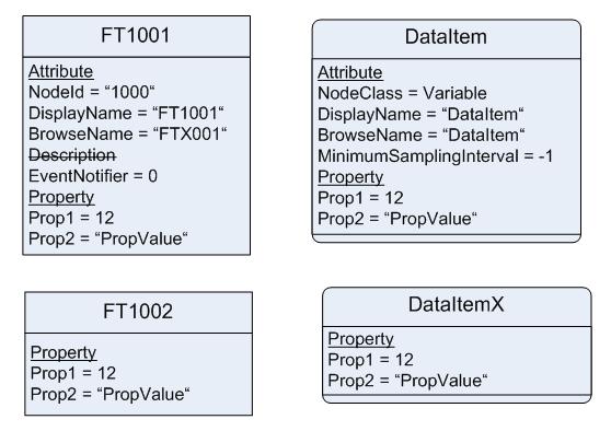
To avoid too many nodes in a figure it is allowed to expose properties inside a node, similar to attributes. Therefore, the text field used for exposing attributes is extended. Under the last text line containing an attribute a new text line containing the underlined text “Property” has to be added. If no attribute is provided, the text has to start with this text line. After this text line, each new text line shall contain a Property, starting with the BrowseName of the Property followed by “=” and the value of the Value attribute of the Property. Figure 4 shows some examples exposing properties inline. It is allowed to expose some properties of a node inline, and other properties as nodes. It is not allowed to show a Property inline and as well as an additional node.
It is allowed to add additional information to a figure using the graphical representation, for example callouts.